At Solideon, after building out the robot work cells for the grinder and welder operations, I was handed a new problem to solve: getting the right shielding gas to each of those cells on demand. The challenge wasn’t just routing three different gas lines (air, pure argon, and an argon/CO₂ mix) across the facility, but giving the operators full remote control over every valve and solenoid while also feeding them live data about line pressure and system status. Designing the brass manifolds was new territory for me, but it turned out to be relatively straightforward compared to the electronics side of things.
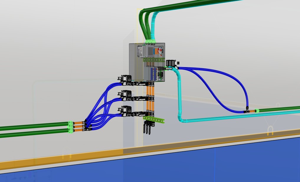
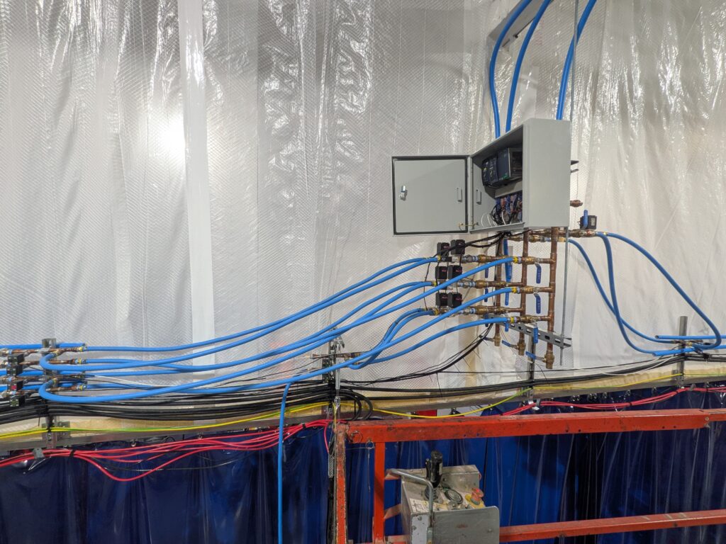
Someone else on the team handled designing and building out the air supply manifold, so I focused on the rest. I ended up designing a total of three separate manifolds minus that one, and we fabricated eleven total: two on the supply side for argon and the mixed gas, two on the output side to feed into three of the four robot cells, and three more for the distribution system itself handling individual gas and air routing. These were all built from off-the-shelf brass tubing and fittings soldered together by a technician who had them fabricated according to my design with a bit of guidance here and there as they went along.
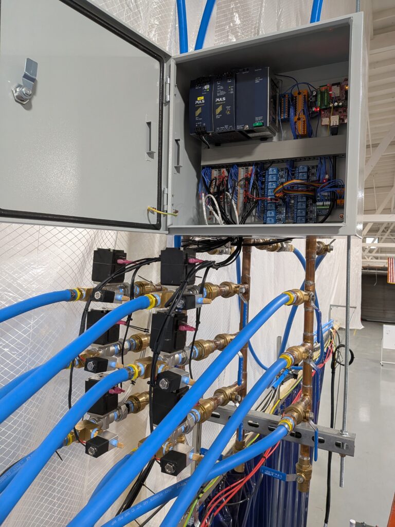
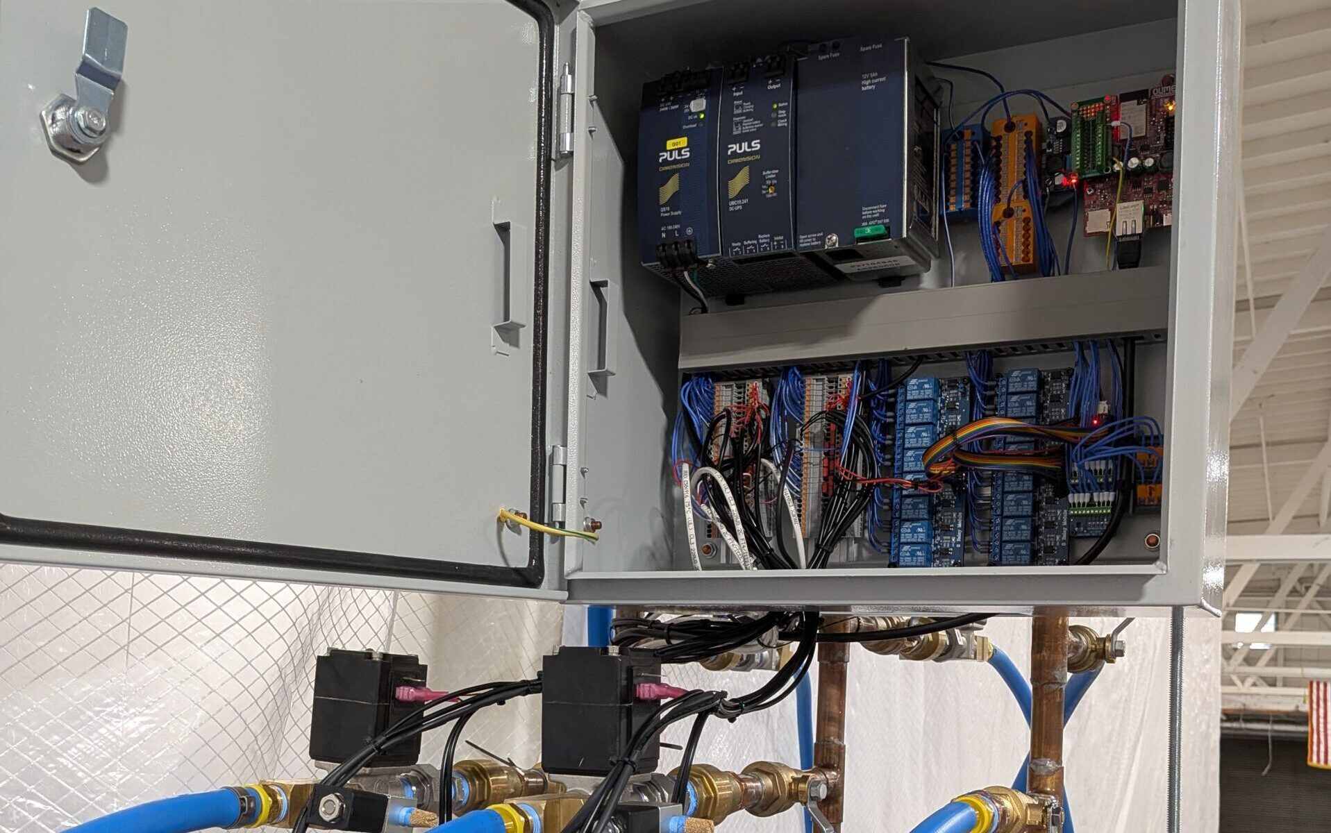
The real heart of the project was building an electronics control box that could manage every valve, solenoid, and pressure sensor in the system. The main controller was another ESP32 board, which felt right given how successful they were with our other IoT deployments at Solideon (more on that in my IoT Environmental Monitoring Deployment post). Inside that box I packed two 8-relay boards, two ADS1115 analog-to-digital converter boards to read the pressure sensors, an MCP23017 I/O expander so I could push more signals off the limited GPIO pins on the ESP32, eight pressure sensors for monitoring each line independently, eight solenoids, and eight motorized ball valves. I also included a power supply with a battery backup UPS to keep everything running during brief interruptions.

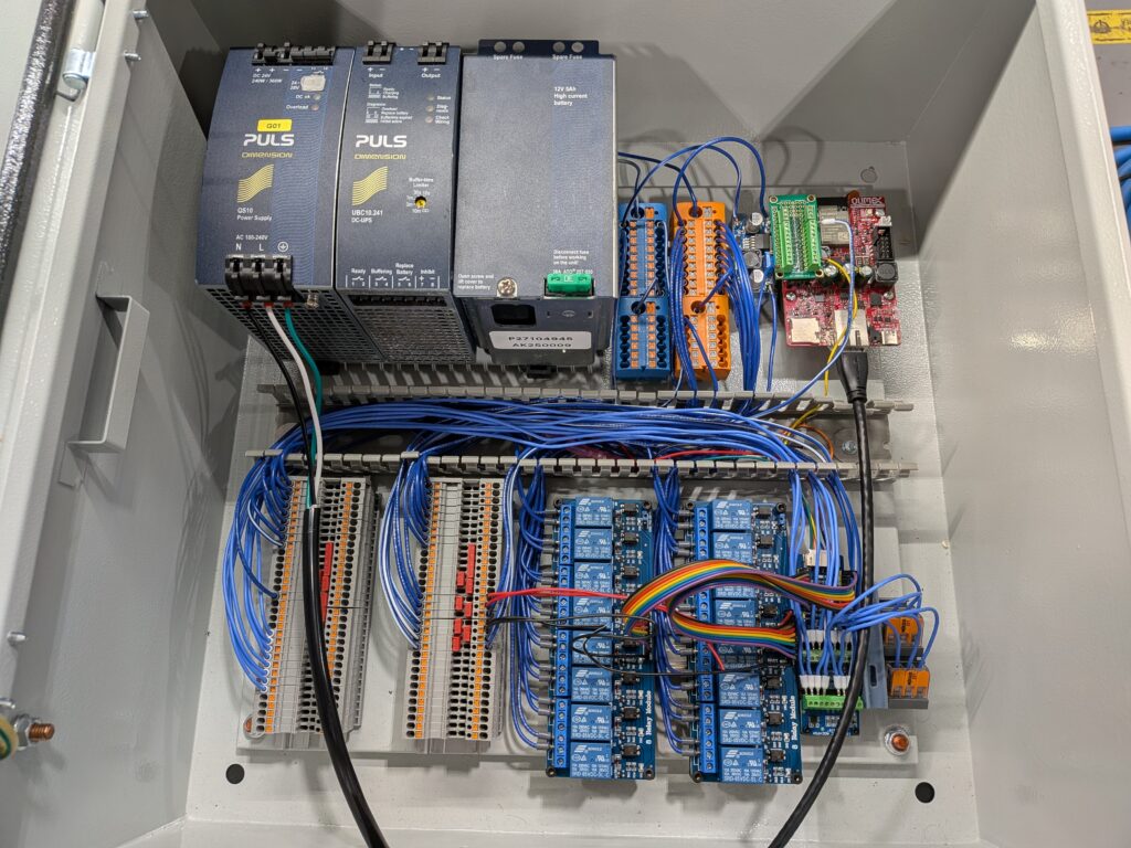
Before any of that hardware went into a box, I planned out the entire electrical layout in Rhino using manufacturer-provided CAD models for every component where I could find them. That way I knew exactly how everything was going to fit before committing to an enclosure size or mounting anything. Once the layout was dialed in, I used Rhino to design custom DIN rail brackets for each of the special components: a buck converter, the ESP32 board itself, the two relay boards, the I/O expander, and both A2D converter boards. I 3D printed all of those brackets on a Bambu Labs X1C FDM printer with PETG.
I started out by writing basic control and sensor-reading scripts in Arduino IDE to get comfortable with each individual component. Opening single valves, reading pressure sensor data through the ADC boards, toggling solenoids through the relay module, testing the I/O expander communication over I2C, the goal was to make sure I had a firm grip on every piece before tying it all together. Along the way, I ran into an issue with some larger solenoids we initially picked up for the job: they weren’t designed to stay in the open position and got uncomfortably hot when energized for extended periods, so those ended up getting swapped out and left on the shelf.
Once all the individual components behaved as expected, I built out the full control script that could be driven remotely via our MQTT network. The ESP32 acted as a client on the network, publishing live sensor changes while also listening for commands from a web dashboard hosted on a separate server. That way operators could open and close any valve or solenoid at will, see real-time line pressure readings, and keep an eye on system status without having to walk over to the electronics box. I’ve covered more of that dashboard in a separate portfolio entry (link coming here once it’s written).
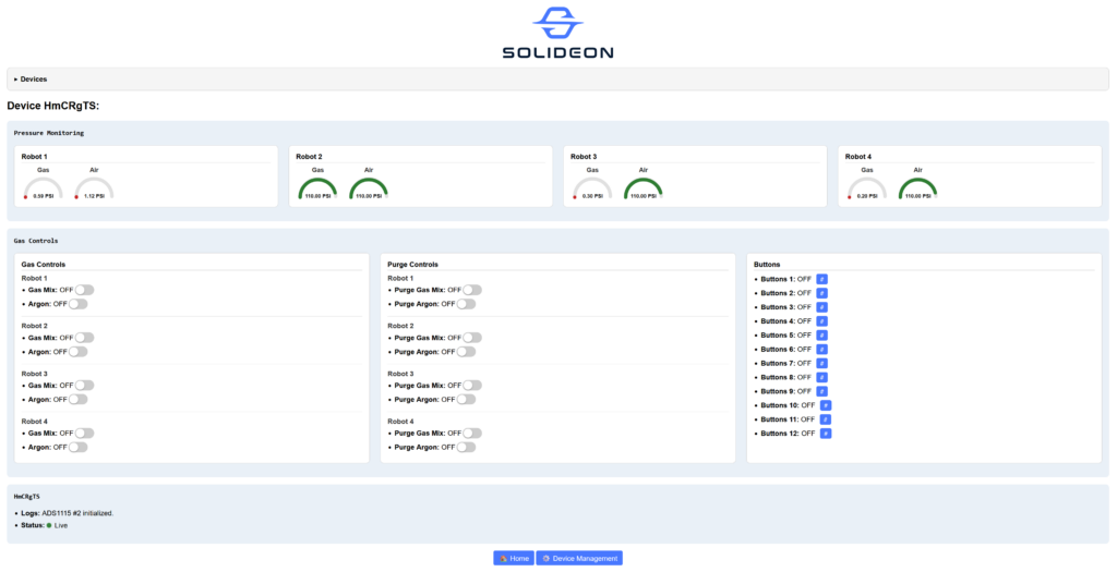
After getting everything wired up and communicating properly, I also programmed the ESP32 to automatically save the current on-off state of every relay to persistent flash memory and restore those exact states on reboot when full power is lost. So if there’s a hard shutdown or battery drain, the system wakes up exactly where it left off rather than defaulting to some unsafe configuration. That felt like an important safety redundancy that I was glad to have built in.
I actually started experimenting with automated purging sequences before we began running actual gas through the lines, but I haven’t had a chance to fully test and optimize them yet, so they’re not quite at a usable stage. For now the system remains manually user-driven from the dashboard, which honestly turned out to be a pretty solid setup for what we needed at the time. The operators had exactly the level of control they wanted without having to worry about whether an automation sequence was going to surprise them mid-shift.
This whole project sat alongside the larger work cell build described in my Industrial Robot Work Cell Design & Fabrication post, and it’s one of those projects where I got to touch pretty much every layer: designing the manifolds, building the electronics enclosure from scratch, wiring everything up, writing the firmware, and then debugging the whole thing once it was deployed. Getting those purging sequences dialed in is still on my list for when time allows, so this one isn’t quite finished yet.